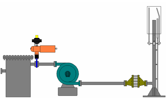
In general, this web page is about the application of landfill gas (LFG) to industry. Commonly I find myself in various location in and out of the US consulting, designing, trouble shooting or starting-up equipment for use with landfill gas. One common way for the landfill to deal with the gas, when it is not put to benficial use is to burn it. Below is an illustration of one type of equipment used for such an application.
The above image is of an open flare. These are also called candle-stick or utlity flares.
The Knock Out Pot (KOP) is used as a particulate and de-watering filter.
Inside the KOP inlet a defector plate is placed to impinge on the gas flow as it enters the KOP. This sudden change in direction imposed by the plate results in heavier particulate being knocked out. These heavier particales strike the plate and are knocked out of the gas stream. After the LFG has made it past the first obstacle, it now passes into the main vessle. THe area of this vessle is much larger than pipe the LFG was traveling in and cause a large reduction in velocity gas. If any of the heavier suspeneded objects had made it past the defelector plate at the inlet, they now drop out in the main vessel.
The final step in the KOP is for the gas to travel through a demisting pad. This filter is typically selected for filtration between 5-20 micron. Any remaining liquid in the gas is captured at this point. Eventually the KOP will fill with liquid and requires draining periodically. Back
While the flare is not prepared for operation the LFG must be prevent from venting. Since landfill gas is combustable and has a very unpleasant oder, the gas is not allowed to vent freely. This valve is permitted to open once the flare has proved an ignition source is available. Anytime the flame is lost, this valve is required to close. Proper operation of this vavle is very imortant. If this valve fails to close environmental agencies may impose fines on the landfill. Back
When the start sequence is initiated the pilot is ignited. Once pilot ignition is proved by temperaure, the blower is started. Back
As the waste breaks down in the landfill it needs to be removed. If the gas is not actively extracted it will be emitted through the surface of the landfill and may move laterally. If it does move laterally, the gas can move out of the landfill. Normally, landfill gas is not found in enough of a concentration to be a problem. But if the gas is not extracted dangerous level can be present. It may end up in buildings in and around the landfill. When the gas is confined, it becomes a potential fire or explosion hazard. This indicates regular and reliable extraction of the gas is required.
Gas extraction blowers used to apply a vacuum on the landfill must provide adequate vacuum to insure the gas does not leave the landfill. This requires good design of the collection system and sizing of the blower(s). Blowers for landfill gas extraction systems may require a total horsepower anywhere from 25HP to 200HP Back
On occasion, the gas extraction may not work properly. If the failure allows the LFG to burn with out the blower, gas may burn back into the system. Should this happen, an explosion may occur, the extraction equipment will be damaged, and if present injury or death of personnel may occur. The flame arrestor prevents the combustion of the gas to continue past the arrestor. The gas can continue to burn at the face of the arrestor. If the gas does continues to burn, it will eventually melt the arrestor and seal of the gas. If this should happen, the flame arrestor will require replacement costing several thousand dollars, with significant down time of the flare. Back
For utility flares the stack elevates the flame to keep it away from people and property. There is significant heat energy present when landfill gas is burned. This can dry out vegetation and start a fire. The height for the flare stack is important design criteria. Back
Proper burner design requires the gas exit the burner tip at a specific velocity for a given flow. Along with the correct exit velocity the proper amount of air must be mixed with the gas. Air mixing is a passive arrangement. This requires the correct size for the windshield. The windshield prevents the wind from blowing out the flame, and contains the heat long enough to allow the thermocouple to detect the flame. Back
At the start of the flare start sequence the pilot is activated. To detect the pilot has been activated and lit, the temperature at the pilot is checked. Once the blower is activated this same thermocouple can be used to confirm main burner ignition. To insure the flare continues burning the temperature at burner is monitored. If the temperature drops below the specified low temperature point the flare system is stopped and the header/inlet valve is closed. Back
As mentioned in the KOP section of this document the KOP is used to collect liquids from the landfill gas (also known as condensate). Once the liquid level is high enough it can carry over into the blower. If the condensate should carry over damage to the blower is likely and it can be severe.
To prevent such an event from occurring, a high level switch is installed in the KOP. If the liquid level should rise too high in the KOP, the flare system is stopped. The flare can not be restarted until the level switch cleared and the reset button pressed Back
Flare inlet temperature is monitored to prevent damage to the flame arrester. If the flame should burn down into the stack the temperature will elevate flare above normal operating temperature. If this should happen the flare system is shut off. It can not restart until the temperature has returned to normal and the flare system reset Back
The UV Flame monitor is a redundant and secondary monitoring system. The UV sensor allows for the quick detection of flame presence and loss. Generally these are required were the compliance regulators have a very short time limit on the emission of unburned gas. The UV flame monitor is considered secondary since it can provide a false positive for flame detection. With the burner open to the natural environment, ambient light from the sun can stimulate the sensor causing it to indicate flame presence. Various methods have been used to limit the opportunity for this to be a problem, but they have downsides as well.
One method was to limit the view of the sensor. With the view restricted it is very unlikely ambient light will bother the sensor, but on the other hand should the wind should blow the flame away from the sensors view (and it does), the flare will shutdown falsely for flame loss To date the best remedies for the UV sensor reliable operation has been to modify the burner design or use multiple UV sensors. Back
To insure the flare is burning the temperature at burner is monitored. If the temperature drops below the specified low temperature point the flare system is stopped and the header/inlet valve is closed. This T/C is use in conjuction with the Pilot T/C Back
Questions and Comments: E-Mail Flare-Guy